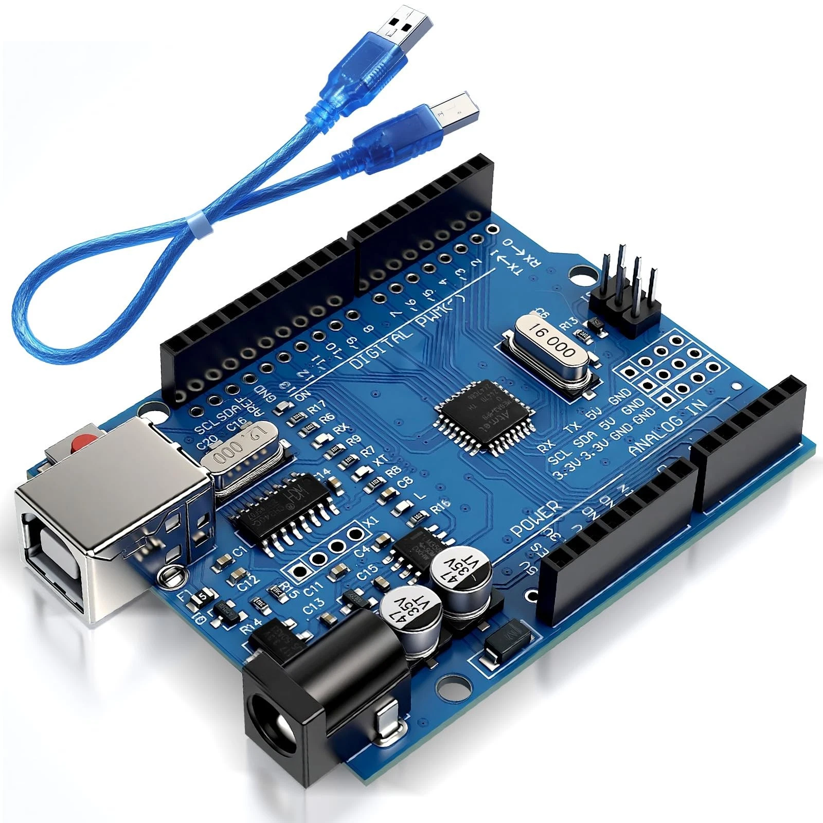
Blink an LED with Arduino
Blink an LED with Arduino: Your First Electronics Project
Project Overview
A blinking LED is a practical starting point for learning Arduino. It teaches you how to build a simple circuit, upload a program, and control an electronic component using code.
In this project, you will connect an external LED to an Arduino Uno R3 and program it to turn on and off repeatedly. You will also learn how the circuit works and how to change the flashing pattern.
What You Will Learn
- How to connect an LED and a current-limiting resistor.
- How to configure an Arduino pin as an output.
- How setup(), loop(), digitalWrite(), and delay() work.
- How to upload a sketch and troubleshoot the circuit.
Components Required
- 1 Arduino Uno R3.
- 1 USB data cable compatible with your board.
- 1 standard red LED.
- 1 330-ohm resistor.
- 1 breadboard and jumper wires.
- A computer with the Arduino IDE installed.
No additional Arduino libraries are needed.
How the Circuit Works
An LED produces light when current flows through it in the correct direction. Its longer leg is usually the anode, while the shorter leg is the cathode. The flat edge on the LED body also usually identifies the cathode.
The resistor limits the current through the LED and protects both the LED and the Arduino output pin. Never leave it out of this circuit.
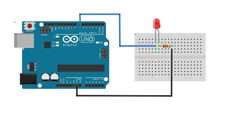
With the wiring below, setting pin 8 to HIGH turns the LED on. Setting it to LOW turns it off. The program uses timed pauses to create the blinking pattern.
Wiring Guide
Disconnect the USB cable before wiring the circuit.
- Place the LED on the breadboard with its legs in separate electrically connected groups of holes.
- Connect Arduino digital pin 8 to one end of the 330-ohm resistor.
- Connect the other end of the resistor to the LED's anode.
- Connect the LED's cathode to an Arduino GND pin.
- Check the connections before reconnecting USB.
Connection path: Pin 8 to resistor, resistor to LED anode, and LED cathode to GND.
On a typical breadboard, a group of five holes on one side of the central gap is connected internally. Placing both LED legs in the same connected group prevents the circuit from working as intended.
Source Code
Create a new sketch in the Arduino IDE and paste in this complete program:
const byte LED_PIN = 8;
const unsigned long ON_TIME = 500;
const unsigned long OFF_TIME = 500;

void setup() {
  // Configure the LED pin as an output.
  pinMode(LED_PIN, OUTPUT);

  // Start with the LED off.
  digitalWrite(LED_PIN, LOW);
}

void loop() {
  // Turn the LED on and wait.
  digitalWrite(LED_PIN, HIGH);
  delay(ON_TIME);

  // Turn the LED off and wait.
  digitalWrite(LED_PIN, LOW);
  delay(OFF_TIME);
}
Code Explanation
Pin and Timing Settings
LED_PIN identifies the digital pin connected to the LED circuit. Its value must match your wiring. The keyword const means this value cannot change while the program runs.
ON_TIME and OFF_TIME specify the delays in milliseconds. Since 1,000 milliseconds equals one second, a value of 500 keeps the LED in each state for half a second.
The setup() Function
setup() runs once when the sketch starts or the board resets. The instruction pinMode(LED_PIN, OUTPUT) configures the pin to control an output. The following instruction sets it LOW so the LED begins in the off state.
The loop() Function
loop() repeats continuously. First, digitalWrite() sets the pin HIGH to turn the LED on. After the first delay, it sets the pin LOW to turn the LED off. The second delay completes the cycle.
With both delays set to 500, one full blink takes approximately one second. The delay() function pauses progress through the main program, which is suitable here. Later projects can use millis() to manage timing while continuing to check inputs.
Upload and Test
- Connect your Arduino Uno to the computer using a USB data cable.
- Select Arduino Uno as the board in the Arduino IDE.
- Select the port associated with your connected board.
- Click Verify to compile the sketch, then click Upload.
- Wait for the upload to finish and observe the external LED.
If the board package is missing, install Arduino AVR Boards through Boards Manager for the Uno R3.
The external LED should stay on for half a second, then off for half a second, repeatedly. Pressing RESET restarts the program. The sketch remains stored on the board after you disconnect power.
Troubleshooting
- LED stays off: Disconnect power and check its polarity, the GND connection, and the breadboard connections. Confirm that the signal wire goes to pin 8.
- LED stays on: Check that the circuit is connected to pin 8 rather than the 5V header, and confirm that the latest upload succeeded.
- Upload fails: Check the selected board and port. Try another USB data cable if the board is not detected.
- Timing changes have no effect: Upload the modified sketch again. Saving the code on your computer does not update the board.
Experiments to Try
Change only the timing constants at the top of the sketch, then upload again:
- Faster blinking: Set both values to 200.
- Slower blinking: Set both values to 1000.
- A brief status flash: Set ON_TIME to 100 and OFF_TIME to 900.
For the last experiment, the full cycle still takes approximately one second, but the LED is on for only a small part of that time.
Practical Applications
This project is ideal for beginners, classroom demonstrations, and checking a new Arduino setup. The same output-control concept is used in status indicators, warning lights, and traffic-light models.
Remember that Arduino output pins are intended for small signals and loads. Motors, pumps, and high-power lights require appropriate driver circuits.
Next Project
Next, you can add a push button to control the LED. This introduces digital inputs and lets your circuit respond to a person instead of following a fixed timing sequence.