Control an LED with a Push Button Using Arduino
Control an LED with a Push Button Using Arduino
Project Overview
In the previous project, your LED blinked automatically. This time, you will control it using a push button.
When you press and hold the button, the LED turns on. When you release the button, the LED turns off. This introduces digital inputs, which allow the Arduino to respond to switches and sensors.
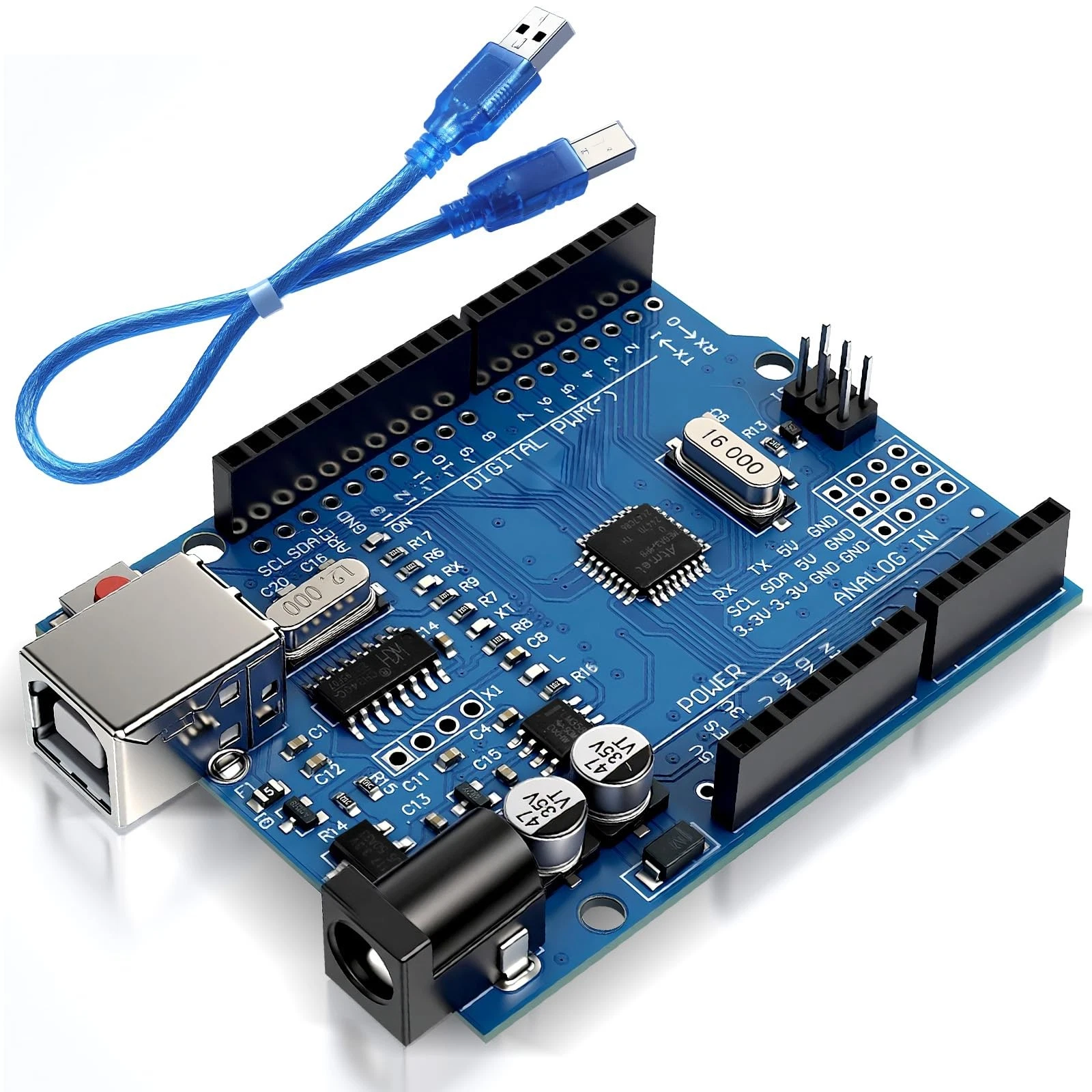
This project uses an Arduino Uno R3 and requires no additional libraries.
What You Will Learn
- How to connect and read a push button.
- How to use the Arduino's internal pull-up resistor.
- How to make decisions using if and else.
- How to control an LED using an input.
Components Required
- 1 Arduino Uno R3.
- 1 compatible USB data cable.
- 1 normally open momentary push button.
- 1 standard LED.
- 1 330-ohm resistor.
- 1 breadboard and jumper wires.
- A computer with the Arduino IDE installed.
How the Project Works
The Arduino repeatedly checks the button and decides whether to turn the LED on or off.
An input without a defined electrical state can produce unpredictable readings. We prevent this by using INPUT_PULLUP, which enables a resistor inside the Arduino.
With the button connected between the input pin and ground:
- Button released: the input reads HIGH.
- Button pressed: the input reads LOW.
The program therefore checks for LOW to detect a press. This may seem reversed at first, but it follows directly from the button connecting the input to ground.
The internal resistor is for the button input. The LED still needs its separate 330-ohm resistor to limit current.
Wiring Guide
Disconnect the Arduino from USB before assembling or changing the circuit.
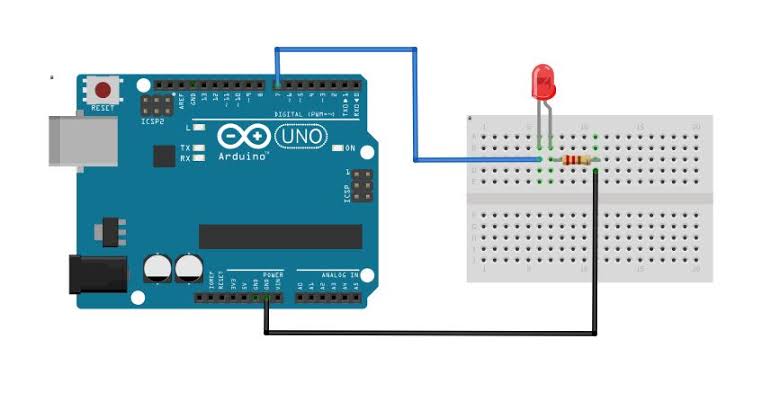
Connect the LED:
- Place the LED on the breadboard with its legs in separate electrically connected groups.
- Connect digital pin 8 to one end of the 330-ohm resistor.
- Connect the resistor's other end to the LED anode, usually the longer leg.
- Connect the LED cathode, usually the shorter leg, to GND.
Connect the push button:
- Place the button on the breadboard.
- Connect digital pin 2 to one switch terminal.
- Connect the other switch terminal to GND.
- Check that pressing the button connects pin 2 to ground.
Many small buttons have four legs arranged as two internally connected pairs. Use one terminal from each pair. If you use two permanently connected legs, the Arduino will detect a continuous press.
If you are unsure about the terminal arrangement, check the button's datasheet or use a multimeter's continuity mode with the circuit disconnected from power.
No connection to the 5V pin is required for the button in this arrangement.
Source Code
Create a new sketch in the Arduino IDE and paste in this complete program:
const int ledPin = 8;
const int buttonPin = 2;

void setup() {
  // Configure the LED as an output.
  pinMode(ledPin, OUTPUT);

  // Enable the internal pull-up resistor.
  pinMode(buttonPin, INPUT_PULLUP);

  // Start with the LED off.
  digitalWrite(ledPin, LOW);
}

void loop() {
  int buttonState = digitalRead(buttonPin);

  if (buttonState == LOW) {
    // The button is pressed.
    digitalWrite(ledPin, HIGH);
  } else {
    // The button is released.
    digitalWrite(ledPin, LOW);
  }

  delay(20);
}
Code Explanation
Choosing the pins: The constants ledPin and buttonPin identify the connections used in the circuit. Their values must match your wiring: the LED connects through its resistor to pin 8, and the button connects to pin 2.
Configuring the circuit: The setup() function runs once when the sketch starts. It configures the LED pin as an output and the button pin as an input with its internal pull-up resistor enabled. It then turns the LED off.
Reading the button: Inside loop(), the following instruction reads the input and stores its current state:
int buttonState = digitalRead(buttonPin);The result is HIGH when the button is released and LOW when it is pressed.
Making a decision: The condition buttonState == LOW checks whether the button is pressed. The double equals sign compares values. If the condition is true, the LED turns on. Otherwise, the else section turns it off.
Adding a short pause: The instruction delay(20) waits 20 milliseconds before the next reading. The delay value is written directly inside the function.
This pause is not a complete button-debouncing solution. Mechanical contacts can briefly bounce when pressed or released. Reliable debouncing becomes especially important when counting presses or switching an LED on and off with successive presses.
Upload and Test
- Connect the Arduino to your computer using the USB data cable.
- Select Arduino Uno and the correct port in the Arduino IDE.
- Click Verify to compile the sketch, then click Upload.
- Leave the button released. The LED should remain off.
- Press and hold the button. The LED should turn on.
- Release the button. The LED should turn off.
If the board package is missing, install Arduino AVR Boards through Boards Manager for the Uno R3.
Repeat the test several times. This project uses momentary control: the LED follows the button and does not stay on after you release it.
Troubleshooting
- The LED is always on: Check whether the button wires use two permanently connected legs. Also check whether pin 2 is accidentally connected directly to ground.
- The LED never turns on: Check the LED polarity, resistor connections, and whether pressing the button connects pin 2 to GND.
- The LED behaves unpredictably: Check for loose wires and confirm that the sketch uses INPUT_PULLUP.
- The sketch will not upload: Check the selected board, port, and USB cable. The cable must support data transfer.
Experiments to Try
Reverse the behavior: Change the condition from buttonState == LOW to buttonState == HIGH. The LED will stay on when the button is released and turn off when pressed.
Explore response time: Temporarily change delay(20) to delay(1000). The Arduino will check the button less often, so short presses may be missed. Restore the shorter delay afterward.
Change the input pin: Disconnect USB, move the button signal wire from pin 2 to pin 3, and change the buttonPin value to 3. Reconnect and upload the modified sketch.
Ideal For
This project is useful for beginners learning interactive circuits, classroom demonstrations, and simple control-panel prototypes. It introduces the input-and-decision pattern used with switches and many digital sensors.
Before continuing, make sure you can explain why a pressed button reads LOW and why the LED still needs its own resistor.
Next Project
Next, you will build a miniature traffic light using red, yellow, and green LEDs. You will learn how to control several outputs and arrange their behavior into a timed sequence.