Blinking LED with Arduino

Project Overview
This project is the starting point for anyone learning Arduino and embedded systems. It introduces how a microcontroller can control hardware using simple programming instructions. You will learn how to configure pins, send electrical signals, and control timing.
The blinking LED is often called the "Hello World" of electronics because it demonstrates the fundamental idea of digital output: turning something ON and OFF programmatically. Understanding this project builds the foundation for controlling more complex components like motors and sensors.
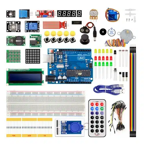
Components Required
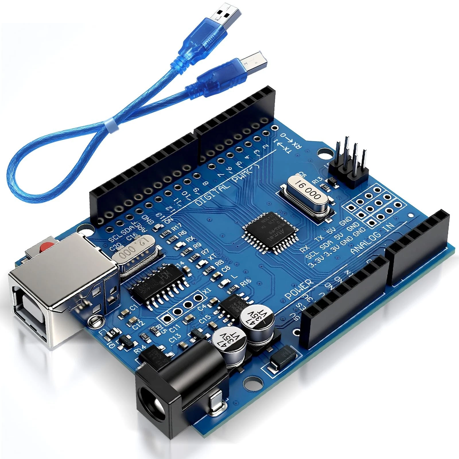
- Arduino Uno
- 1 LED (Light Emitting Diode)
- 220Ω Resistor
- Breadboard (optional)
- Jumper wires
Wiring Guide
Follow these steps carefully:
- Insert the LED into the breadboard.
- Identify the legs: the longer leg is the anode (+), and the shorter leg is the cathode (-).
- Connect a 220Ω resistor to the anode (long leg). This protects the LED from excessive current.
- Connect the other end of the resistor to digital pin 13 on the Arduino.
- Connect the cathode (short leg) directly to the GND pin on the Arduino.
Without the resistor, too much current could flow and permanently damage the LED.
Source Code
int led = 13;

void setup() {
  pinMode(led, OUTPUT);
}

void loop() {
  digitalWrite(led, HIGH);
  delay(1000);
  digitalWrite(led, LOW);
  delay(1000);
}
Code Explanation
The variable led stores the pin number connected to the LED. In setup(), we configure this pin as an OUTPUT so the Arduino can send voltage through it.
The loop() function runs continuously. Inside it, digitalWrite(led, HIGH) sends 5V to the LED, turning it ON. After a delay of 1 second, digitalWrite(led, LOW) turns it OFF by removing the voltage. This cycle repeats indefinitely, creating a blinking effect.
This simple logic introduces timing and control, which are essential in all embedded systems.