Traffic Light System

Project Overview
This project builds on the blinking LED concept by introducing multiple outputs and sequential control. You will simulate a real-world traffic light system using three LEDs: red, yellow, and green.
The goal is to understand how embedded systems manage timed sequences and state changes. This is an important concept used in automation, industrial machines, and robotics.
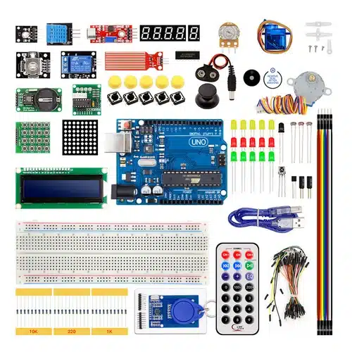
Components Required
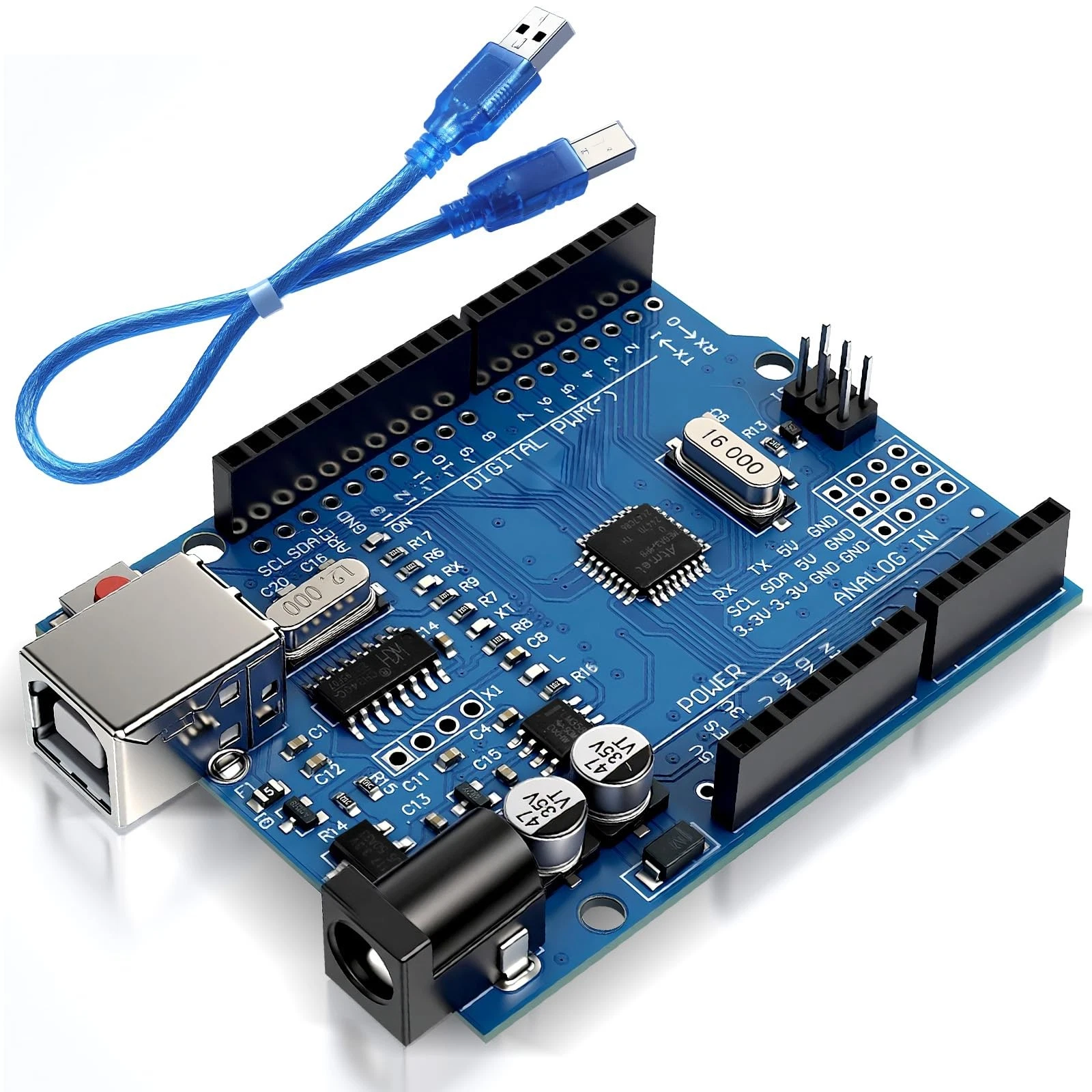
- Arduino Uno
- 3 LEDs (Red, Yellow, Green)
- 3 x 220Ω Resistors
- Breadboard
- Jumper wires
Wiring Guide
Follow these steps:
- Insert the three LEDs into the breadboard.
- Connect a resistor to each LED's anode (long leg).
- Connect:
- Red LED → Pin 2
- Yellow LED → Pin 3
- Green LED → Pin 4
- Connect all cathodes (short legs) to the ground rail.
- Connect the ground rail to Arduino GND.
Each resistor ensures that the LEDs receive safe current levels.
Source Code
int red = 2;
int yellow = 3;
int green = 4;

void setup() {
  pinMode(red, OUTPUT);
  pinMode(yellow, OUTPUT);
  pinMode(green, OUTPUT);
}

void loop() {
  digitalWrite(green, HIGH);
  delay(5000);
  digitalWrite(green, LOW);

  digitalWrite(yellow, HIGH);
  delay(2000);
  digitalWrite(yellow, LOW);

  digitalWrite(red, HIGH);
  delay(5000);
  digitalWrite(red, LOW);
}
Code Explanation
Each LED is assigned to a digital pin. In the setup(), all pins are configured as outputs.
The loop() function controls the sequence:
- Green turns ON for 5 seconds (go signal)
- Yellow turns ON for 2 seconds (warning)
- Red turns ON for 5 seconds (stop)
This sequence repeats continuously, mimicking a real traffic light system. This introduces the idea of a state machine, where the system transitions between defined states.