Build a Mini Traffic Light with Arduino
Build a Mini Traffic Light with Arduino
Project Overview
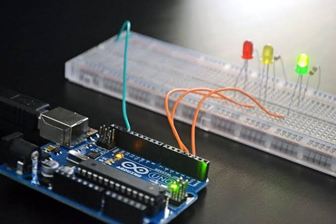
In the previous project, you controlled an LED with a push button. This project introduces multiple outputs by using red, yellow, and green LEDs to build a miniature traffic light.
The Arduino will turn on the green LED for five seconds, the yellow LED for two seconds, and the red LED for five seconds. The sequence then repeats automatically.
This is a simplified educational model for one traffic signal. It does not control an intersection or represent every country's traffic-light sequence.
What You Will Learn
- How to connect multiple LEDs to separate digital pins.
- Why each LED needs its own resistor.
- How to create a sequence using digitalWrite() and delay().
- How to keep only the intended LED switched on.
Components Required
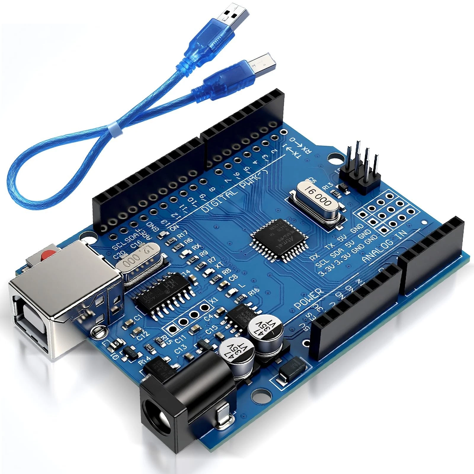
- 1 Arduino Uno R3.
- 1 USB data cable.
- 1 red LED.
- 1 yellow LED.
- 1 green LED.
- 3 resistors, each 330 ohms.
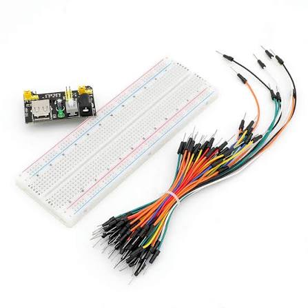
- 1 breadboard.
- Jumper wires.
- A computer with the Arduino IDE installed.
No additional libraries are required. Remove the previous project's button wiring before building this circuit.
How the Project Works
Each LED connects to its own Arduino output pin through a resistor. The Arduino controls the LEDs independently, switching them on and off in a fixed order.
- Green: stays on for five seconds.
- Yellow: stays on for two seconds.
- Red: stays on for five seconds.
Only one LED is on during each stage. The program turns the current LED off before turning the next one on.
Each LED needs its own resistor to limit its current. Do not connect an LED directly between an Arduino output pin and ground.
Wiring Guide
Disconnect USB before making connections. Arrange the LEDs vertically with red at the top, yellow in the middle, and green at the bottom.
Red LED:
- Connect digital pin 8 to one end of a 330-ohm resistor.
- Connect the resistor's other end to the red LED's anode.
- Connect the red LED's cathode to the breadboard ground rail.
Yellow LED:
- Connect digital pin 9 to a second 330-ohm resistor.
- Connect the resistor's other end to the yellow LED's anode.
- Connect the yellow LED's cathode to the same ground rail.
Green LED:
- Connect digital pin 10 to the third 330-ohm resistor.
- Connect the resistor's other end to the green LED's anode.
- Connect the green LED's cathode to the same ground rail.
Finally, connect an Arduino GND pin to the ground rail. If your breadboard rail is split in the middle, use one continuous section or bridge the split with a jumper.
The longer LED leg is usually the anode. The shorter leg and flat edge on the LED body usually identify the cathode. Keep each LED's legs in separate electrically connected groups on the breadboard.
Source Code
Create a new sketch and paste in this complete program:
const int redLed = 8;
const int yellowLed = 9;
const int greenLed = 10;

void setup() {
  // Configure all three LED pins as outputs.
  pinMode(redLed, OUTPUT);
  pinMode(yellowLed, OUTPUT);
  pinMode(greenLed, OUTPUT);

  // Start with every LED off.
  digitalWrite(redLed, LOW);
  digitalWrite(yellowLed, LOW);
  digitalWrite(greenLed, LOW);
}

void loop() {
  // Green light: stay on for 5 seconds.
  digitalWrite(greenLed, HIGH);
  delay(5000);
  digitalWrite(greenLed, LOW);

  // Yellow light: stay on for 2 seconds.
  digitalWrite(yellowLed, HIGH);
  delay(2000);
  digitalWrite(yellowLed, LOW);

  // Red light: stay on for 5 seconds.
  digitalWrite(redLed, HIGH);
  delay(5000);
  digitalWrite(redLed, LOW);
}
Code Explanation
Pin definitions: The constants redLed, yellowLed, and greenLed identify the output pins. Their values must match the wiring: red on pin 8, yellow on pin 9, and green on pin 10.
Initial setup: The setup() function runs once when the Arduino starts or resets. It configures all three pins as outputs and sets them LOW so the LEDs begin switched off.
Green stage: The program sets the green LED pin HIGH, waits five seconds, and then sets it LOW.
digitalWrite(greenLed, HIGH);
delay(5000);
digitalWrite(greenLed, LOW);
Yellow and red stages: The same pattern is repeated for the yellow and red LEDs, using delays of 2000 and 5000 milliseconds.
Repeating the sequence: When loop() reaches its closing brace, it starts again. The green LED therefore lights after the red stage finishes.
There are 1000 milliseconds in one second. The complete sequence takes approximately 12 seconds: five seconds green, two seconds yellow, and five seconds red.
Upload and Test
- Check the wiring and connect the Arduino to your computer.
- Select Arduino Uno and the correct port in the Arduino IDE.
- Click Verify, then Upload.
- Watch the LEDs complete at least two full cycles.
- Confirm that the order is green, yellow, red, then green again.
- Check that only one LED stays on at a time.
If the Uno R3 board package is missing, install Arduino AVR Boards through Boards Manager.
Press RESET to restart the program. After startup, the sequence begins with green again.
Troubleshooting
- No LEDs light: Check the USB connection and the jumper between Arduino GND and the breadboard ground rail.
- One LED stays off: Disconnect power and check its polarity, resistor, and breadboard connections.
- The colors appear in the wrong order: Check that the red, yellow, and green circuits connect to pins 8, 9, and 10 respectively.
- Several LEDs light together: Check for shared breadboard connections between their anodes and confirm that the uploaded sketch matches the example.
- Timing changes have no effect: Upload the modified sketch again. Saving it on your computer does not update the Arduino.
Experiments to Try
- Change the green delay to 8000 to make the green stage last eight seconds.
- Set all three delays to 1000 to create a faster demonstration.
- Build a cardboard traffic-light housing and label each color.
- Predict the total cycle time after changing the delays, then check it with a stopwatch.
The delay() function pauses progress through the main program. This works for a fixed sequence, but a future pedestrian-button project will need more responsive timing so button presses are not missed during long waits.
Ideal For
This project suits beginners, classroom demonstrations, and model-road displays. It develops confidence with multiple outputs, shared ground connections, and timed sequences.
Next Project
Next, you will control LED brightness using a potentiometer. You will learn how to read an adjustable input and use pulse-width modulation to change how bright an LED appears.