Control LED Brightness with a Potentiometer
Control LED Brightness with a Potentiometer
Project Overview
In the previous project, you controlled an LED using a push button. This time, you will adjust the brightness of an LED by turning a knob.
The knob belongs to a potentiometer, a component that provides an adjustable voltage. The Arduino reads this voltage and uses it to control the LED's brightness.
This project introduces analog inputs and pulse-width modulation, commonly called PWM. These concepts are useful for adjustable lighting, control panels, and other interactive projects.
What You Will Learn
- How to connect a potentiometer as an adjustable voltage divider.
- How to read an analog input using analogRead().
- How to convert a sensor reading into a useful output range.
- How to adjust LED brightness using analogWrite().
Components Required
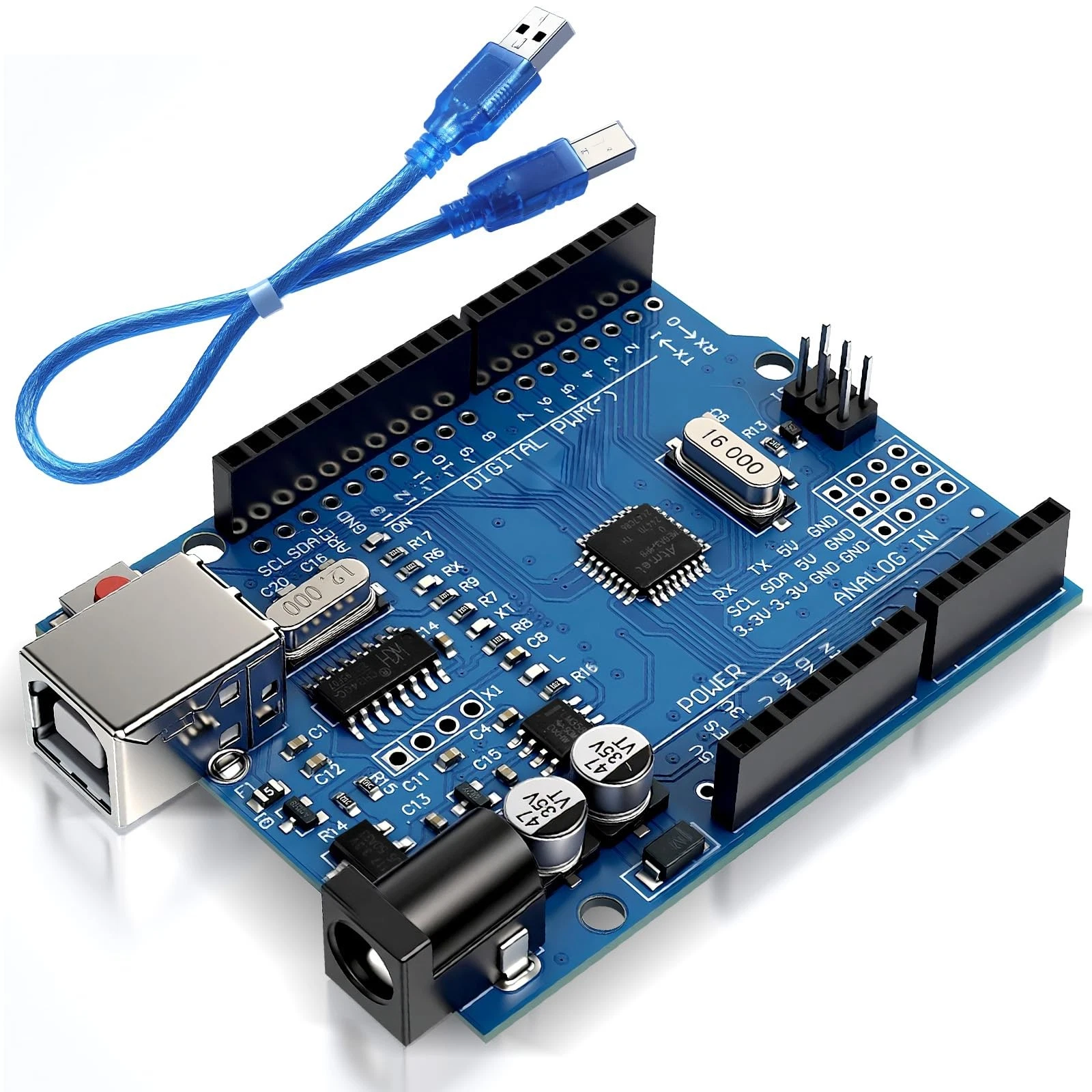
- 1 Arduino Uno R3.
- 1 USB data cable.
- 1 standard LED.
- 1 330-ohm resistor.
- 1 10-kilohm linear potentiometer.
- 1 breadboard.
- Jumper wires.
- A computer with the Arduino IDE installed.
No additional libraries are required. The reading ranges and pin choices in this guide apply to the Arduino Uno R3.
How the Project Works
A typical potentiometer has three terminals: two ends of a resistive track and a movable contact called the wiper. On a common three-pin rotary potentiometer, the middle terminal is the wiper.
Connecting the outer terminals to 5V and GND allows the wiper to provide a voltage between those two levels as you turn the knob. The Arduino measures this voltage through analog input A0.
On the Uno R3, analogRead() normally returns a value from 0 to 1023. The program converts this into a value from 0 to 255 for analogWrite().
On a PWM pin, analogWrite() rapidly switches the output on and off. A higher value keeps the output on for a larger fraction of each cycle, making the LED appear brighter. It does not produce a continuously adjustable analog voltage on this pin.
Wiring Guide
Disconnect USB before wiring the circuit.
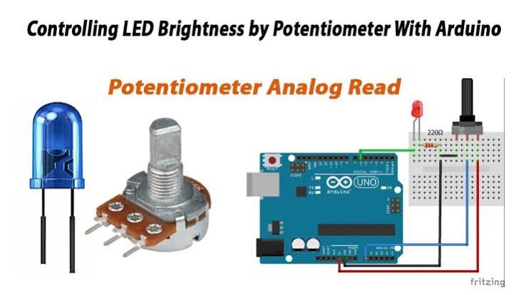
Connect the potentiometer:
- Place the potentiometer on the breadboard with its terminals in separate connected groups.
- Connect one outer terminal to Arduino 5V.
- Connect the other outer terminal to Arduino GND.
- Connect the middle terminal, or wiper, to analog pin A0.
Check the component's pin arrangement if it differs from a standard three-pin potentiometer. Swapping the two outer connections reverses which turning direction increases brightness.
Connect the LED:
- Connect digital pin 9 to one end of the 330-ohm resistor.
- Connect the resistor's other end to the LED anode, usually the longer leg.
- Connect the LED cathode, usually the shorter leg, to Arduino GND.
Pin 9 supports PWM on the Uno R3 and is marked with a tilde symbol on the board. Keep the resistor in the LED circuit to limit current.
Both the potentiometer and LED must share the Arduino's ground connection.
Source Code
Use this complete sketch:
const int potentiometerPin = A0;
const int ledPin = 9;

void setup() {
  pinMode(ledPin, OUTPUT);
  analogWrite(ledPin, 0);
}

void loop() {
  // Read the potentiometer: 0 to 1023.
  int sensorValue = analogRead(potentiometerPin);

  // Convert the reading to a PWM value: 0 to 255.
  int brightness = map(sensorValue, 0, 1023, 0, 255);

  // Adjust the LED brightness.
  analogWrite(ledPin, brightness);

  delay(10);
}
Code Explanation
Pin settings: The potentiometerPin constant identifies analog input A0. The ledPin constant identifies PWM output pin 9. These values must match your wiring.
Initial setup: The setup() function configures the LED pin as an output and sets its brightness to zero. The analog input does not need an additional pinMode() instruction for this example.
Reading the knob: The instruction below measures the voltage at A0 and stores the reading:
int sensorValue = analogRead(potentiometerPin);A reading near zero means the wiper voltage is close to ground. A reading near 1023 means it is close to the analog reference voltage, normally the board's 5V supply in this setup.
Converting the range: The map() function scales the input range of 0 to 1023 into the output range of 0 to 255:
int brightness = map(sensorValue, 0, 1023, 0, 255);A reading near the middle of the input range produces a PWM value near the middle of the output range. This gives approximately half the on-time, although your eyes may not perceive it as exactly half brightness.
Updating the LED: The analogWrite() instruction applies the brightness value to pin 9. Zero keeps the output off, while 255 keeps it fully on. Values between them produce PWM.
Brief pause: The delay(10) instruction waits ten milliseconds before the next reading. Turning the knob should still produce a quick visible response.