Build a Parking Distance Indicator
Build a Parking Distance Indicator
Project Overview
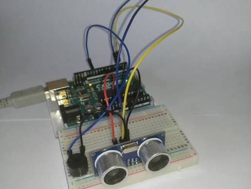
In the previous project, you detected objects using an infrared sensor. This time, you will combine an ultrasonic sensor, three LEDs, and a buzzer to build a parking distance indicator.
The Arduino measures the distance to an object and selects a coloured indicator. As the object gets closer, the indication changes from green to yellow and then red. A buzzer adds an audible warning.
This is a tabletop learning project, not a vehicle safety device. It brings together sensor readings, decisions, and multiple outputs in one program.
What You Will Learn
- How to combine a sensor with several outputs.
- How to divide distance readings into different zones.
- How to generate sound using tone() and noTone().
- How to handle missing or out-of-range measurements.
- How delays affect the response of a larger program.
Components Required
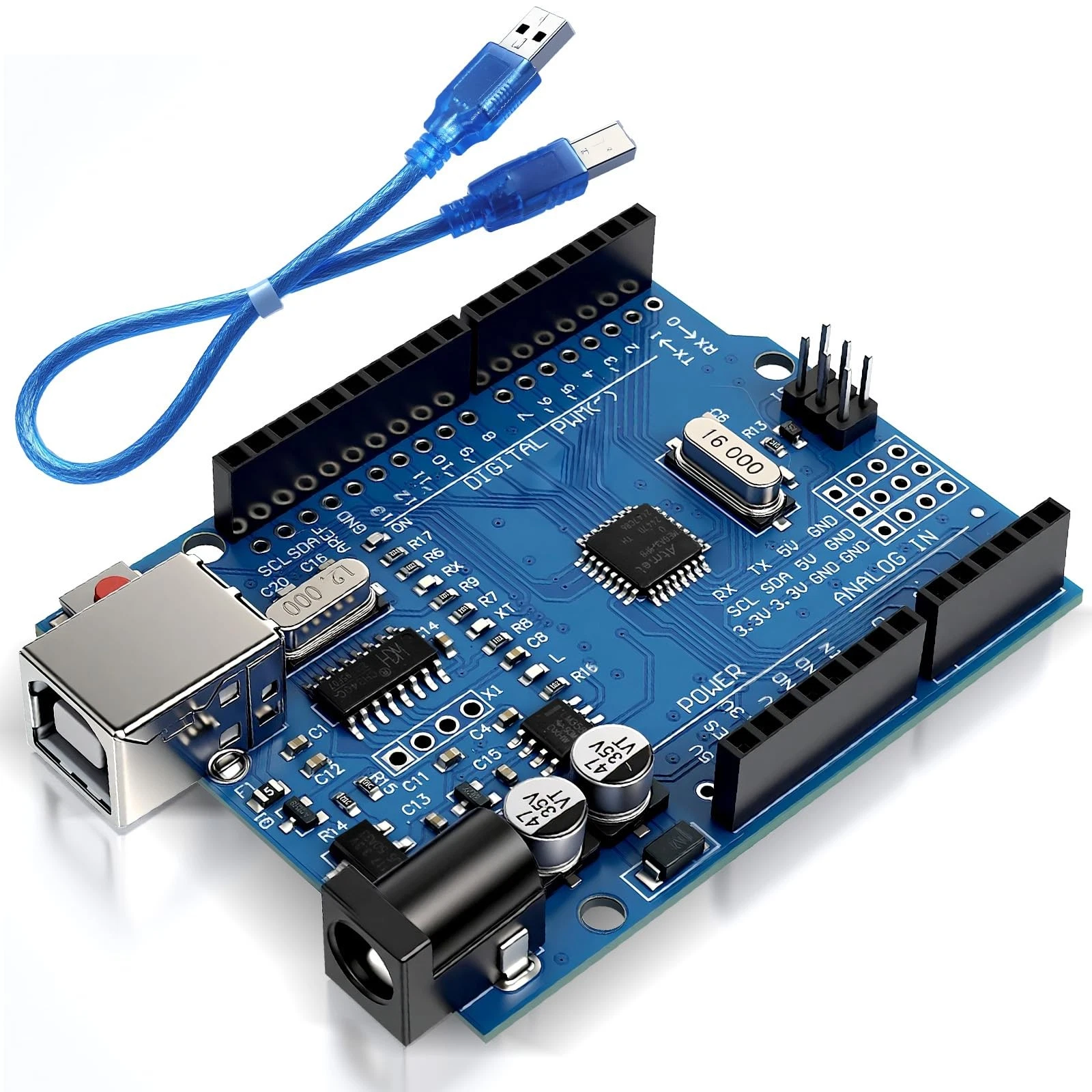
- 1 Arduino Uno R3 and USB data cable.
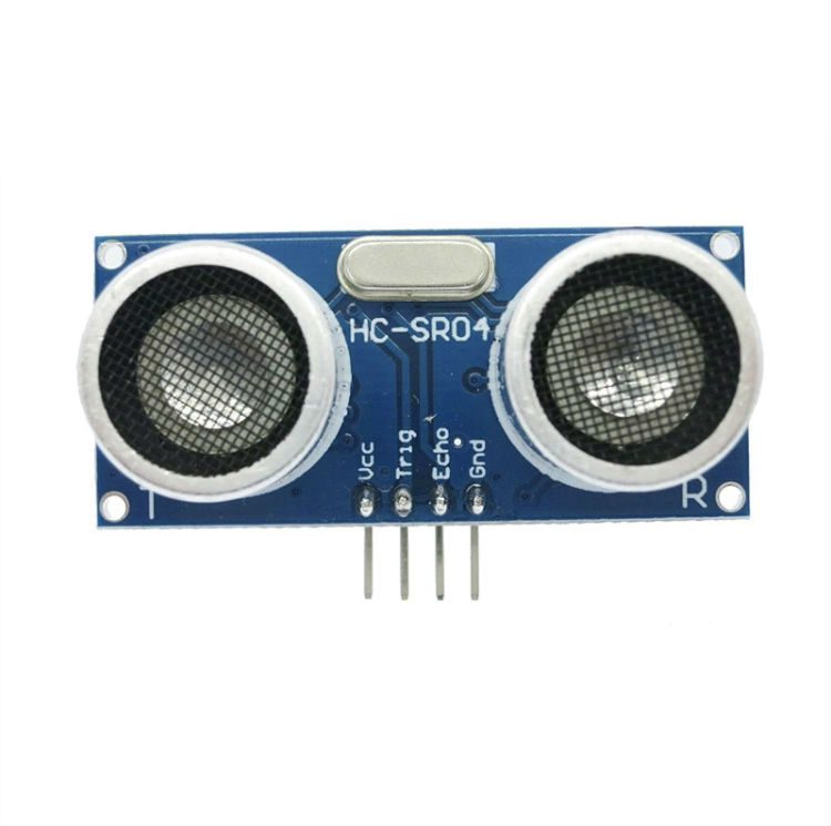
- 1 standard 5V HC-SR04 ultrasonic sensor.
- 1 red LED, 1 yellow LED, and 1 green LED.
- 3 resistors of 330 ohms, one for each LED.
- 1 small passive piezo sounder suitable for Arduino output signals.
- 1 additional 330-ohm resistor for the piezo connection.
- 1 breadboard and jumper wires.
- A flat object, such as a book or piece of cardboard.
- A computer with the Arduino IDE installed.
No additional libraries are required. Use a passive piezo sounder rather than an active buzzer or a low-resistance speaker. An active buzzer contains its own oscillator and behaves differently.
How the Project Works
The HC-SR04 sends out ultrasound and reports the time taken for an echo to return. The Arduino converts that time into distance and selects one of three zones:
- More than 50 centimetres: green LED on, buzzer silent.
- More than 20 and up to 50 centimetres: yellow LED on, repeating short beeps.
- From 2 to 20 centimetres: red LED on, continuous tone.
If no echo is received, or the calculated distance falls outside 2 to 400 centimetres, all three LEDs turn off and the buzzer stops. The Serial Monitor displays a measurement error. This state means the distance is unknown, not that the area is clear.
Use a large, flat target facing the sensor. Soft, narrow, or angled objects may produce unreliable readings.
Wiring Guide
Disconnect USB before making connections. Connect Arduino GND to a breadboard ground rail and use that rail for all ground connections. Bridge any split in the rail if your circuit uses both sections.
Connect the ultrasonic sensor:
- Connect VCC to Arduino 5V.
- Connect GND to the ground rail.
- Connect TRIG to digital pin 9.
- Connect ECHO to digital pin 10.
This connection is intended for the 5V Uno R3. A standard HC-SR04 Echo output needs suitable voltage reduction before connection to a 3.3V-only input.
Connect the LEDs:
- Connect digital pin 2 through a 330-ohm resistor to the green LED's anode.
- Connect digital pin 3 through a separate 330-ohm resistor to the yellow LED's anode.
- Connect digital pin 4 through another 330-ohm resistor to the red LED's anode.
- Connect all three LED cathodes to the ground rail.
The anode is usually the longer leg. The cathode is usually the shorter leg and is also identified by a flat edge on the LED body. Each LED must have its own resistor.
Connect the piezo sounder:
- Connect digital pin 8 through the remaining 330-ohm resistor to the piezo's positive terminal.
- Connect its negative terminal to the ground rail.
Follow any polarity markings on the sounder. Keep the sensor facing away from nearby breadboard parts so they do not become unintended targets.
Source Code
Use this complete sketch:
const int triggerPin = 9;
const int echoPin = 10;

const int greenLed = 2;
const int yellowLed = 3;
const int redLed = 4;
const int buzzerPin = 8;

void setup() {
  pinMode(triggerPin, OUTPUT);
  pinMode(echoPin, INPUT);

  pinMode(greenLed, OUTPUT);
  pinMode(yellowLed, OUTPUT);
  pinMode(redLed, OUTPUT);
  pinMode(buzzerPin, OUTPUT);

  digitalWrite(triggerPin, LOW);
  digitalWrite(greenLed, LOW);
  digitalWrite(yellowLed, LOW);
  digitalWrite(redLed, LOW);
  digitalWrite(buzzerPin, LOW);

  Serial.begin(9600);
}

void loop() {
  // Start an ultrasonic measurement.
  digitalWrite(triggerPin, LOW);
  delayMicroseconds(2);
  digitalWrite(triggerPin, HIGH);
  delayMicroseconds(10);
  digitalWrite(triggerPin, LOW);

  // Wait up to 30 milliseconds for the echo.
  long duration = pulseIn(echoPin, HIGH, 30000);
  float distanceCm = duration * 0.0343 / 2.0;

  // Reject missing or out-of-range readings.
  if (duration == 0 ||
      distanceCm < 2.0 ||
      distanceCm > 400.0) {
    digitalWrite(greenLed, LOW);
    digitalWrite(yellowLed, LOW);
    digitalWrite(redLed, LOW);
    noTone(buzzerPin);

    Serial.println("Distance unknown.");
    delay(100);
    return;
  }

  Serial.print("Distance: ");
  Serial.print(distanceCm, 1);
  Serial.println(" cm");

  if (distanceCm > 50.0) {
    // Far zone: green light, no sound.
    digitalWrite(yellowLed, LOW);
    digitalWrite(redLed, LOW);
    digitalWrite(greenLed, HIGH);

    noTone(buzzerPin);
    delay(100);

  } else if (distanceCm > 20.0) {
    // Middle zone: yellow light, short beeps.
    digitalWrite(greenLed, LOW);
    digitalWrite(redLed, LOW);
    digitalWrite(yellowLed, HIGH);

    tone(buzzerPin, 2000);
    delay(100);
    noTone(buzzerPin);
    delay(300);

  } else {
    // Near zone: red light, continuous tone.
    digitalWrite(greenLed, LOW);
    digitalWrite(yellowLed, LOW);
    digitalWrite(redLed, HIGH);

    tone(buzzerPin, 2000);
    delay(100);
  }
}
Code Explanation
Pin settings: The constants identify the sensor connections, three LED outputs, and piezo output. Their values must match the wiring.
Initial setup: The setup() function configures each pin and starts with the LEDs and sounder off. Serial.begin(9600) enables distance messages in the Serial Monitor at 9600 baud.
Starting the measurement: The program sends a ten-microsecond HIGH pulse to TRIG. It then measures the HIGH pulse on ECHO using:
long duration = pulseIn(echoPin, HIGH, 30000);The final argument sets a timeout of 30000 microseconds. The duration is stored in a long variable, which comfortably holds the possible result for this measurement.
Calculating distance: Multiplying the duration by 0.0343 converts the sound's approximate travel time into centimetres. Dividing by two accounts for the journey to the object and back.
Checking the measurement: The first if statement rejects a zero duration or a distance outside the expected range. The double vertical bars mean OR: any one of these conditions is enough to enter the error branch.
The return instruction ends the current loop() call after displaying the error. Arduino then calls loop() again, allowing another measurement. This prevents an invalid reading from activating a normal distance indicator.
Selecting a zone: The program first checks whether the distance is above 50 centimetres. If that is false, it checks whether it is above 20 centimetres. Any remaining valid distance belongs to the red zone. Each branch turns the other two LEDs off.
Generating a sound: The following instruction starts a 2000-hertz tone:
tone(buzzerPin, 2000);The frequency controls pitch, not volume. The tone continues until noTone() stops it or another tone instruction changes it.
Creating intermittent beeps: In the yellow zone, the program plays the tone for 100 milliseconds and then remains silent for 300 milliseconds. In the red zone, it leaves the tone running between measurements.
Understanding response time: The yellow-zone delays add up to 400 milliseconds, during which the main program does not take another distance reading. The displayed zone can therefore lag behind a moving object. Readings near a boundary can also make the indicator alternate between zones because this version does not include filtering or hysteresis.
Moving beyond delays: This project demonstrates how several components work together, but more responsive systems need timing that allows other work to continue. In the next project, you will run multiple tasks using millis(), beginning the intermediate section of the series.