Run Multiple Tasks Using millis()
Run Multiple Tasks Using millis()
Project Overview
You saw that delay() pauses progress through the main program, preventing it from checking inputs during that pause. This project introduces millis(), which lets you schedule actions while keeping the main loop running. One LED will blink automatically while a second LED responds to a push button.
The Arduino still executes instructions one after another. However, by checking each task quickly instead of stopping to wait, it can manage both behaviours without a long delay between them.
What You Will Learn
- How millis() measures elapsed time.
- How to blink an LED without delay().
- How to keep a button responsive while another task runs.
- How to remember an output's state between loop iterations.
- Why Arduino timestamps need an appropriate data type.
Components Required
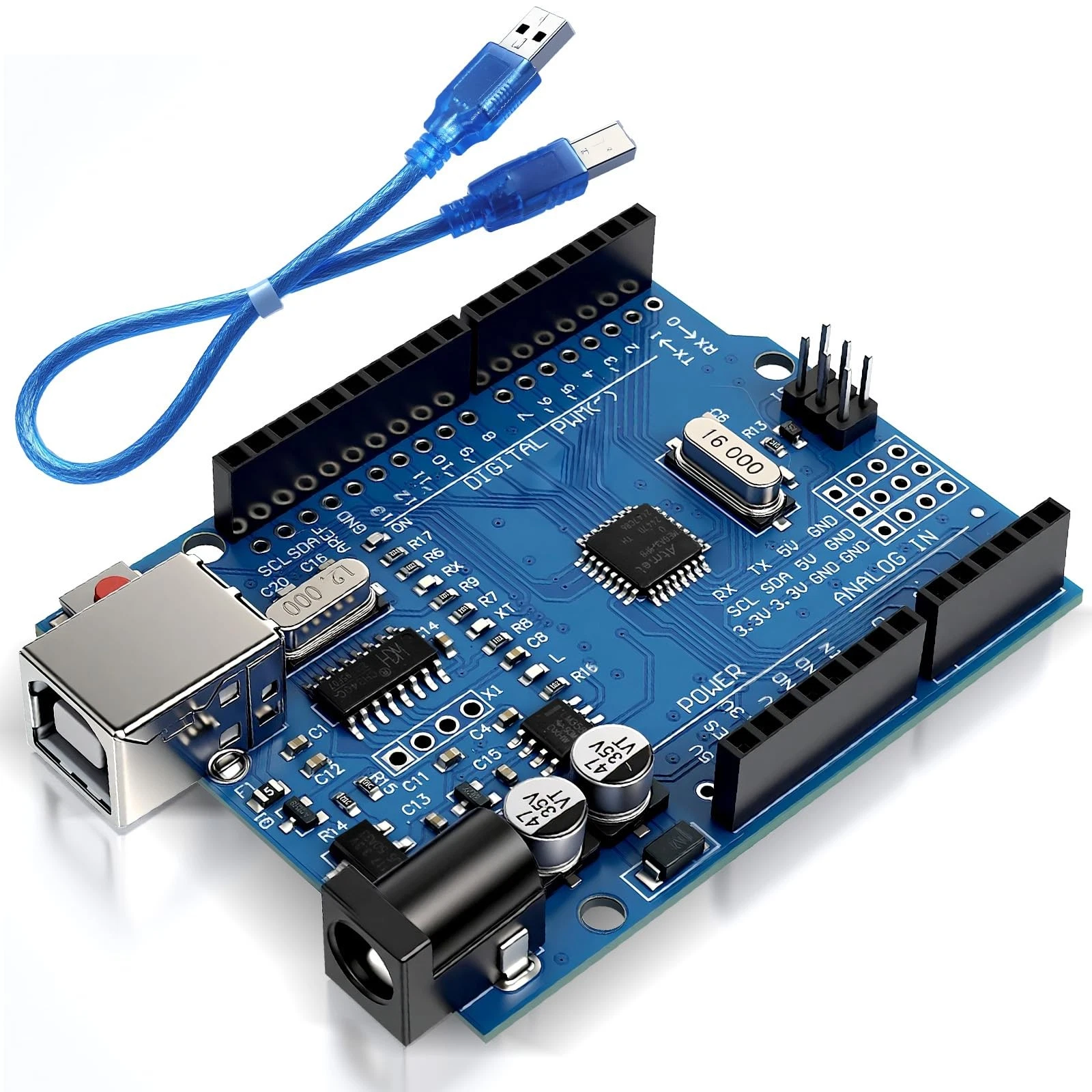
- 1 Arduino Uno R3.
- 1 USB data cable.
- 2 standard LEDs, preferably different colours.
- 2 resistors of 330 ohms, one for each LED.
- 1 normally open momentary push button.
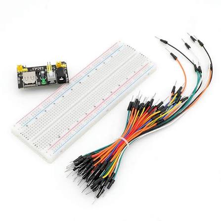
- 1 breadboard and jumper wires.
- A computer with the Arduino IDE installed.
How the Project Works
The millis() function returns the number of milliseconds since the Arduino started running its program. Instead of pausing for a fixed time, the sketch checks how much time has passed since the blinking LED last changed state.
When at least 500 milliseconds have passed, the program switches that LED to its opposite state and records the current time. Otherwise, it continues without changing the LED.
The button is checked during every pass through loop(). Holding it down lights the second LED, while releasing it turns that LED off. The first LED continues blinking independently.
A 500-millisecond interval between state changes gives approximately half a second on and half a second off, producing a complete blink cycle of about one second.
Wiring Guide
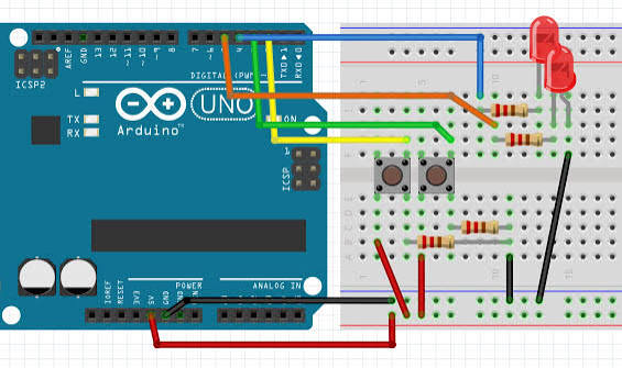
Connect the blinking LED:
- Connect digital pin 8 to one end of a 330-ohm resistor.
- Connect the resistor's other end to the LED anode, usually the longer leg.
- Connect the LED cathode, usually the shorter leg, to GND.
Connect the button-controlled LED:
- Connect digital pin 9 to the second 330-ohm resistor.
- Connect the resistor's other end to the second LED's anode.
- Connect the second LED's cathode to GND.
Connect the button:
- Connect digital pin 2 to one switch terminal.
- Connect the other switch terminal to GND.
For a four-legged button, use one terminal from each internally connected pair. The selected terminals should connect to each other only when the button is pressed.
The sketch uses INPUT_PULLUP, so no external button resistor is needed. Each LED still requires its own current-limiting resistor.
Source Code
Use this complete sketch:
const int blinkLed = 8;
const int buttonLed = 9;
const int buttonPin = 2;

unsigned long previousBlinkTime = 0;
bool blinkState = false;

void setup() {
  pinMode(blinkLed, OUTPUT);
  pinMode(buttonLed, OUTPUT);
  pinMode(buttonPin, INPUT_PULLUP);

  digitalWrite(blinkLed, LOW);
  digitalWrite(buttonLed, LOW);

  previousBlinkTime = millis();
}

void loop() {
  unsigned long currentTime = millis();

  // Task 1: change the blinking LED every 500 ms.
  if (currentTime - previousBlinkTime >= 500UL) {
    previousBlinkTime = currentTime;

    blinkState = !blinkState;
    digitalWrite(blinkLed, blinkState ? HIGH : LOW);
  }

  // Task 2: check the button on every loop.
  int buttonState = digitalRead(buttonPin);

  if (buttonState == LOW) {
    digitalWrite(buttonLed, HIGH);
  } else {
    digitalWrite(buttonLed, LOW);
  }
}
Code Explanation
Pin settings: The blinkLed constant identifies pin 8, which controls the automatically blinking LED. The buttonLed constant identifies pin 9, while buttonPin identifies the input on pin 2.
Remembering the last change: The previousBlinkTime variable stores the timestamp of the last LED change. It is declared outside the functions so its value remains available between calls to loop().
Using unsigned long: Unlike the earlier sketches that put numbers directly inside delay(), this sketch must store timestamps returned by millis(). On the Uno R3, unsigned long is the appropriate 32-bit type for those values. Using the smaller int type would not hold the timer's full range.
Remembering the LED state: The bool variable blinkState holds either true or false. It starts as false, matching the LED's initial off state.
Initial setup: The setup() function configures the outputs, enables the button's internal pull-up resistor, and turns both LEDs off. It then records the starting time for the first blink interval.
Reading the current time: Each pass through loop() begins with:
unsigned long currentTime = millis();This reads the timer without pausing the program. The value is a timestamp, not a waiting instruction.
Checking elapsed time: The program subtracts the previous timestamp from the current timestamp:
if (currentTime - previousBlinkTime >= 500UL) {The result is the time elapsed since the last LED change. The condition becomes true when at least 500 milliseconds have passed. The UL suffix marks 500 as an unsigned long number; the interval is still written directly in the comparison.
For example, if the last change happened at 1000 milliseconds and the current reading is 1500, the elapsed time is 500 milliseconds, so the LED changes state.
Updating the timestamp: The instruction previousBlinkTime = currentTime starts a new interval from the moment this change is handled. This is suitable for a simple indicator, although it is not a precision scheduling system.
Switching the LED state: The exclamation mark means NOT:
blinkState = !blinkState;If blinkState was false, it becomes true. If it was true, it becomes false. The following output instruction chooses HIGH for true and LOW for false:
digitalWrite(blinkLed, blinkState ? HIGH : LOW);The question mark and colon form a compact conditional expression. They select one of two values according to the condition before the question mark.
Reading the button independently: The button code sits outside the blink-timing condition, so it runs on every pass through loop(). Because INPUT_PULLUP is enabled, pressing the button produces LOW. Holding the button lights the second LED without stopping the first LED's blinking.
Handling timer rollover: On the Uno R3, millis() wraps back to zero after approximately 49.7 days. Unsigned subtraction keeps this short elapsed-time comparison working across that rollover, provided the loop continues checking regularly. Do not replace it with a comparison against a future timestamp formed by adding 500.
Understanding responsiveness: There is no delay() in this sketch, so the button is checked frequently. However, millis() does not automatically make other operations non-blocking. Adding a long delay or a blocking sensor read would still hold up both tasks.
Preparing for reliable button events: This project follows the button's current state rather than counting presses. Mechanical contact bounce can produce several rapid changes during a press. In the next project, you will build a button-controlled counter with debouncing so each deliberate press is counted once.