Detect Objects with an Infrared Sensor
Detect Objects with an Infrared Sensor
Project Overview
In the previous project, you measured distance using an ultrasonic sensor. This time, you will use an infrared sensor to detect when an object enters its sensing area.
The sensor emits infrared light and checks for light reflected by nearby objects. When it detects sufficient reflection, the Arduino turns on an LED and displays a message in the Serial Monitor.
This project introduces digital sensor inputs and adjustable detection sensitivity. Unlike the ultrasonic project, this circuit reports whether an object is detected rather than measuring its distance in centimetres.
What You Will Learn
- How a reflective infrared sensor detects objects.
- How to connect a digital sensor output to an Arduino.
- How to interpret an active-low signal.
- How to adjust a sensor's detection threshold.
- How surface colour and surrounding light affect detection.
Components Required
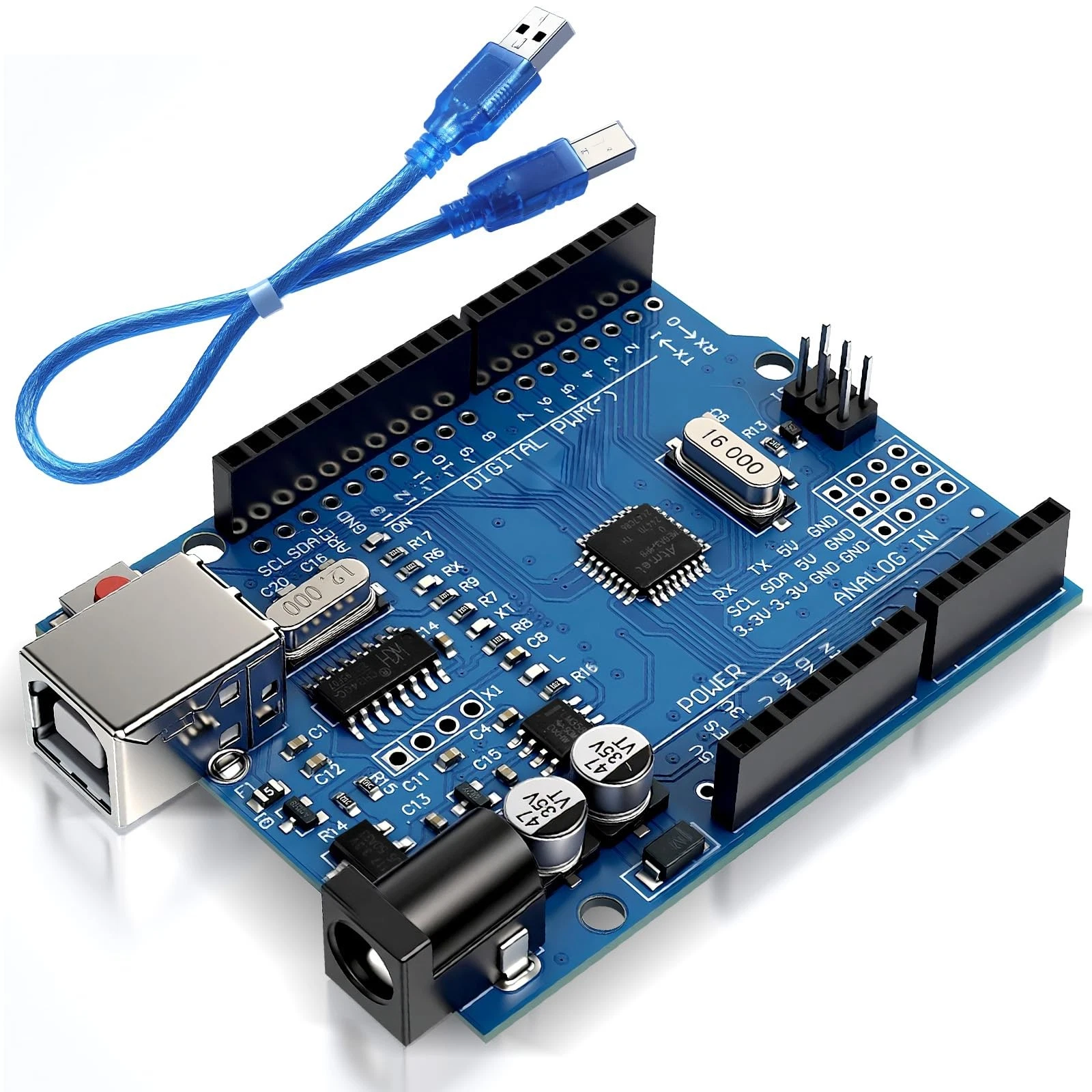
- 1 Arduino Uno R3.
- 1 USB data cable.
- 1 adjustable infrared obstacle-detection module with a digital output and support for 5V operation.
- 1 standard LED.
- 1 330-ohm resistor.
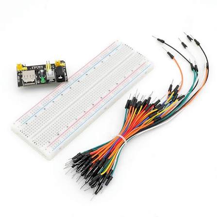
- 1 breadboard and jumper wires.
- A small flat object, such as a piece of cardboard.
- A computer with the Arduino IDE installed.
No additional libraries are required. Use a reflective obstacle-detection module with an infrared emitter and receiver, not a PIR motion sensor or a television remote-control receiver.
The code assumes the module outputs LOW when an object is detected. Check your module's documentation because some sensors use the opposite signal.
How the Project Works
The module contains an infrared emitter and a receiver. The emitter shines infrared light forward. When an object reflects enough of that light toward the receiver, the module changes its digital output.
A small adjustment screw, or trimmer potentiometer, changes the detection threshold. This affects how readily the module responds, but it does not set an exact distance.
For the active-low module used in this example:
- LOW: an object is detected.
- HIGH: no object is detected.
Light-coloured objects often reflect more infrared light than dark objects. The object's angle, size, material, and surrounding light also affect the result. Begin indoors, away from direct sunlight, using a flat piece of light-coloured cardboard.
Wiring Guide
Disconnect USB before making the connections.
Connect the infrared sensor:
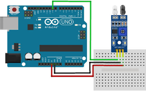
- Connect the sensor's VCC pin to Arduino 5V, after confirming that the module supports 5V operation.
- Connect the sensor's GND pin to Arduino GND.
- Connect the sensor's OUT, DO, or DOUT pin to digital pin 2.
Read the labels on your module because the pin order varies. If the module also has an AO or AOUT pin, leave that analog output disconnected for this project.
Connect the LED:
- Connect digital pin 9 to one end of the 330-ohm resistor.
- Connect the resistor's other end to the LED anode, usually the longer leg.
- Connect the LED cathode, usually the shorter leg, to GND.
Both the sensor and LED must share the Arduino's ground connection. Keep the LED's legs in separate electrically connected breadboard groups.
Adjust the sensor: Once the circuit is powered and the sketch is running, place the cardboard a short distance in front of the sensor. Slowly adjust the trimmer until detection changes reliably when you insert and remove the cardboard. Avoid forcing the screw beyond its travel limits.
Source Code
Use this complete sketch:
const int sensorPin = 2;
const int ledPin = 9;

void setup() {
  pinMode(sensorPin, INPUT);
  pinMode(ledPin, OUTPUT);

  digitalWrite(ledPin, LOW);
  Serial.begin(9600);
}

void loop() {
  // Read the sensor's digital output.
  int sensorState = digitalRead(sensorPin);

  if (sensorState == LOW) {
    // Active-low sensor: LOW means detection.
    digitalWrite(ledPin, HIGH);
    Serial.println("Object detected.");
  } else {
    digitalWrite(ledPin, LOW);
    Serial.println("No object detected.");
  }

  delay(100);
}
Code Explanation
Pin settings: The sensorPin constant identifies digital pin 2, which receives the module's output. The ledPin constant identifies digital pin 9, which controls the external LED.
Initial setup: The setup() function configures the sensor pin as an input and the LED pin as an output. The module supplies the digital signal, so this example uses INPUT. It assumes the module provides a defined HIGH and LOW output, including any pull-up required by its output circuit.
Starting serial communication: Serial.begin(9600) enables text output to the computer. Open the Serial Monitor at 9600 baud to read the detection messages.
Reading the sensor: The following instruction checks the signal at pin 2 and stores it:
int sensorState = digitalRead(sensorPin);The result is HIGH or LOW. Unlike analogRead(), digitalRead() does not return a range of values representing signal strength.
Detecting an object: The condition sensorState == LOW checks whether the active-low module has detected an object. The double equals sign compares values. When the condition is true, the LED turns on and the program prints an object-detected message.
Clearing the indication: When the sensor reads HIGH, the else section turns the LED off and prints that no object is detected. The LED follows the current sensor reading rather than remaining on after an object has moved away.
Matching your sensor: If your module's documentation specifies HIGH when an object is detected, change the condition to:
if (sensorState == HIGH) {Replace only the corresponding condition in the complete sketch. Confirm the signal behaviour with your module's documentation and observations rather than assuming every infrared sensor works identically.
Understanding the result: A detection message means the reflected signal crossed the module's threshold. It does not identify the object or establish its exact distance. A dark or angled object may remain undetected even when it is nearby.
Brief pause: The delay(100) instruction waits 100 milliseconds between readings, producing roughly ten updates per second. Objects that pass through the sensing area very quickly may be missed. In the next project, you will build a parking distance indicator using an ultrasonic sensor, LEDs, and a buzzer.