Build an Automatic Night Light with an LDR
Build an Automatic Night Light with an LDR
Project Overview
In the previous project, you adjusted LED brightness by turning a potentiometer . This time, you will use a light-dependent resistor to switch an LED on automatically when the surroundings become dark.
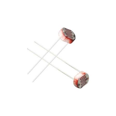
A light-dependent resistor, commonly called an LDR, changes its resistance according to the light falling on it. The Arduino reads this change and decides whether the LED should be on or off. This project introduces automatic control using a sensor.
What You Will Learn
- How an LDR responds to changes in light.
- How to build a voltage divider for an analog input.
- How to switch an LED using sensor readings.
- How two switching thresholds help prevent flickering.
Components Required
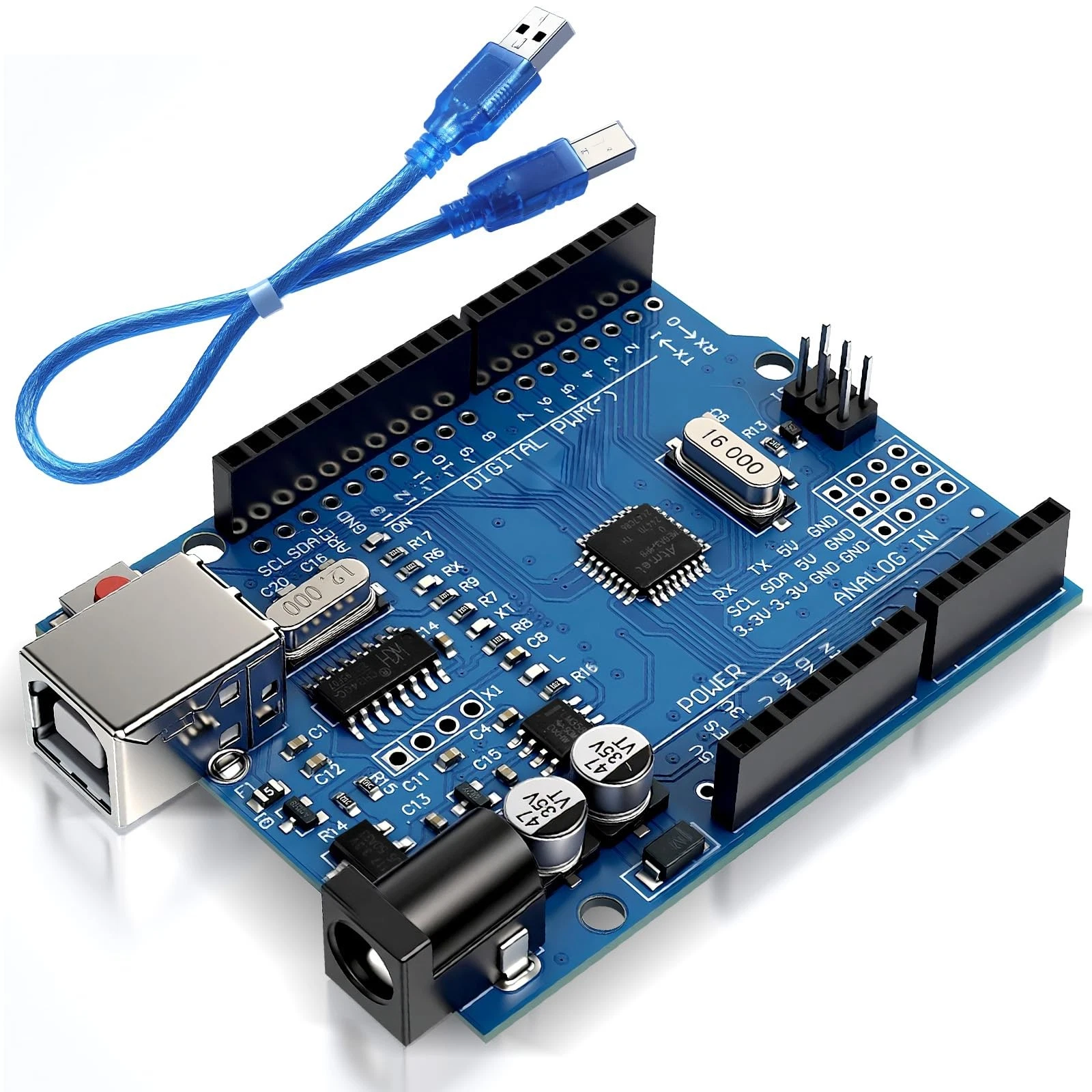
- 1 Arduino Uno R3.
- 1 USB data cable.
- 1 light-dependent resistor.
- 1 10-kilohm resistor.
- 1 standard LED.
- 1 330-ohm resistor.
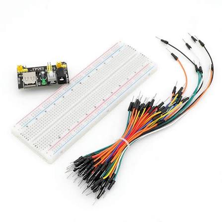
- 1 breadboard and jumper wires.
- A computer with the Arduino IDE installed.
No additional libraries are required. This project uses a bare two-terminal LDR rather than a sensor module.
How the Project Works
An LDR normally has lower resistance in bright light and higher resistance in darkness. Connecting it with a fixed resistor creates a voltage divider, which turns the resistance change into a voltage the Arduino can measure.
With the wiring below, bright light produces a higher reading at A0, while darkness produces a lower reading. The Uno R3 normally reports analog readings between 0 and 1023.
The program turns the LED on when the reading falls below 400. It turns the LED off when the reading rises above 500. Between those values, the LED keeps its current state.
This gap between the switching thresholds is called hysteresis. It helps prevent repeated switching when the light level fluctuates near a single threshold. The values 400 and 500 are starting points and may need adjustment for your LDR and room.
Wiring Guide
Disconnect USB before building the circuit.
Connect the LDR and voltage divider:
- Connect one LDR terminal to Arduino 5V.
- Connect the other LDR terminal to a separate breadboard group. This will be the sensor junction.
- Connect the sensor junction to analog pin A0.
- Connect one end of the 10-kilohm resistor to the same sensor junction.
- Connect the resistor's other end to Arduino GND.
The LDR has no polarity, so either terminal can connect to 5V. The junction shared by the LDR, resistor, and A0 is essential for measuring the changing voltage.
Connect the LED:
- Connect digital pin 9 to one end of the 330-ohm resistor.
- Connect the resistor's other end to the LED anode, usually the longer leg.
- Connect the LED cathode, usually the shorter leg, to GND.
Keep the LED pointed away from the LDR. Otherwise, the LED's own light may affect the reading and cause unwanted switching.
Source Code
Use this complete sketch:
const int ldrPin = A0;
const int ledPin = 9;

void setup() {
  pinMode(ledPin, OUTPUT);
  digitalWrite(ledPin, LOW);

  Serial.begin(9600);
}

void loop() {
  // Read the light level.
  int lightLevel = analogRead(ldrPin);

  // Display the reading for calibration.
  Serial.print("Light level: ");
  Serial.println(lightLevel);

  if (lightLevel < 400) {
    // Dark surroundings: turn the LED on.
    digitalWrite(ledPin, HIGH);
  } else if (lightLevel > 500) {
    // Bright surroundings: turn the LED off.
    digitalWrite(ledPin, LOW);
  }

  // Between 400 and 500, keep the current LED state.
  delay(100);
}
Code Explanation
Pin settings: The ldrPin constant identifies analog input A0, which connects to the voltage-divider junction. The ledPin constant identifies digital output pin 9.
Initial setup: The setup() function configures the LED pin as an output and starts with the LED off. Serial.begin(9600) enables communication with the Serial Monitor at 9600 baud.
Reading the light level: The following instruction measures the voltage at A0 and stores the result:
int lightLevel = analogRead(ldrPin);For this wiring arrangement, covering the LDR should reduce the reading. Shining light on it should increase the reading. These are raw sensor values, not calibrated measurements in lux.
Displaying the reading: Serial.print() writes a label, and Serial.println() prints the reading followed by a new line. Open the Serial Monitor at 9600 baud to observe readings in bright and dark conditions.
Turning the LED on: The first condition checks whether the reading is below 400. If it is, the Arduino sets pin 9 HIGH and lights the LED.
Turning the LED off: The second condition checks whether the reading is above 500. If it is, the Arduino sets pin 9 LOW and switches the LED off.
Keeping the previous state: When the reading is between 400 and 500, including either boundary, neither condition changes the output. The LED therefore remains in its previous state. If the Arduino starts within this range, the LED stays off until the reading falls below 400.
Adjusting the thresholds: Observe readings under the conditions you consider dark and bright. Choose a lower threshold for switching on and a higher threshold for switching off. For example, if darkness gives readings around 200 and bright conditions give readings around 750, the initial thresholds may be suitable. Your actual readings will depend on the components and lighting.
Brief pause: The delay(100) instruction pauses for 100 milliseconds between readings. This provides roughly ten updates per second, which is sufficient for a simple night-light demonstration . In the next project, you will measure distance using an ultrasonic sensor.