Measure Distance with an Ultrasonic Sensor
Measure Distance with an Ultrasonic Sensor
Project Overview
In the previous project, you built an automatic night light using an LDR. This time, you will use an ultrasonic sensor to measure how far away an object is.
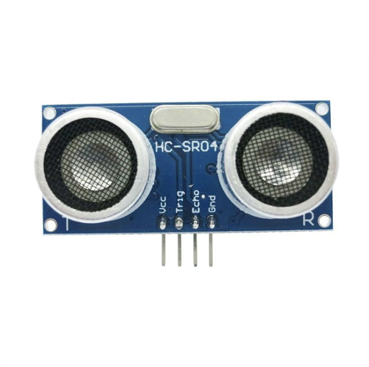
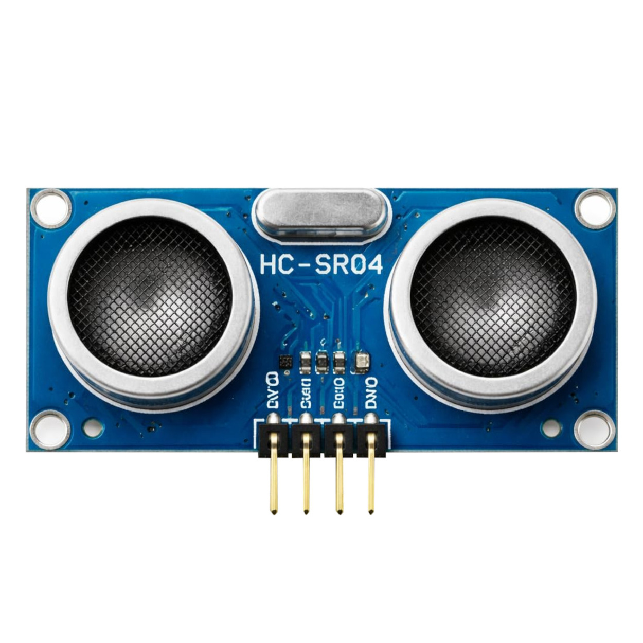
The HC-SR04 sensor sends out a short burst of sound and detects its reflection. The Arduino uses the time taken for the echo to return to calculate distance, then displays the result in the Serial Monitor.
This project introduces distance sensing, which is useful in parking indicators, obstacle-detection systems, and simple robots.
What You Will Learn
- How an ultrasonic sensor measures distance.
- How to connect the HC-SR04 to an Arduino Uno.
- How to generate a short trigger pulse.
- How to measure a pulse using pulseIn().
- How to handle a missing echo without displaying a false distance.
Components Required
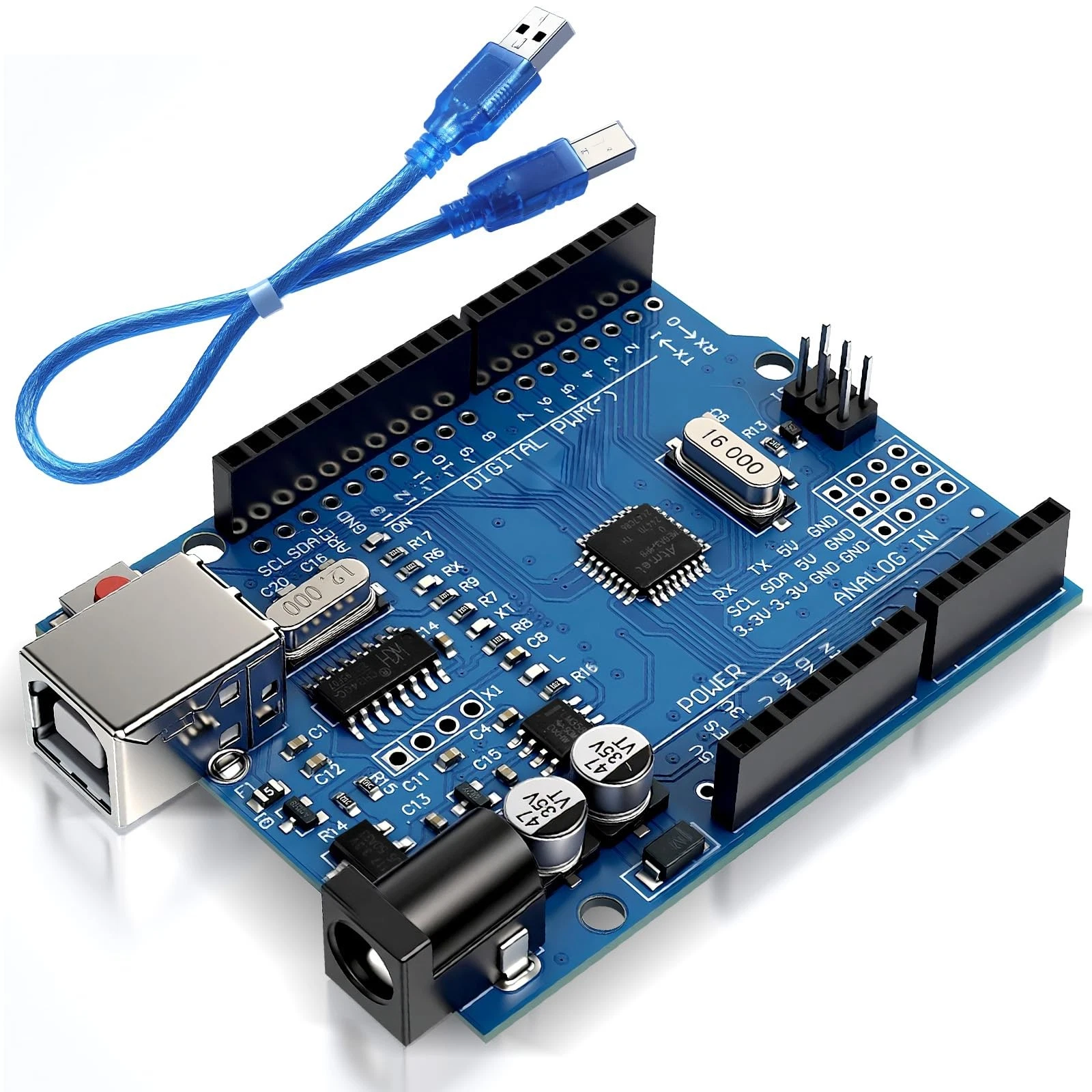
- 1 Arduino Uno R3.
- 1 USB data cable.
- 1 standard 5V HC-SR04 ultrasonic sensor.
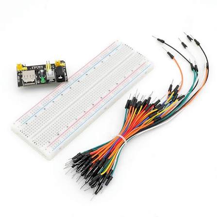
- Jumper wires suitable for the sensor's pins.
- 1 breadboard, if needed for connections.
- A computer with the Arduino IDE installed.
- A ruler and a flat object, such as a book, for comparison.
No additional libraries are required. This wiring is intended for the 5V Arduino Uno R3. The standard HC-SR04 Echo signal must not be connected directly to a 3.3V-only input without suitable voltage reduction.
How the Project Works
The sensor has four pins: VCC, TRIG, ECHO, and GND. The Arduino sends a short pulse to TRIG to start a measurement. The sensor then emits ultrasound and uses the ECHO signal to report the round-trip travel time.
To estimate distance, the program multiplies the measured time by the approximate speed of sound and divides by two. The division is necessary because the sound travels to the object and back.
Using approximately 0.0343 centimetres per microsecond for the speed of sound, the calculation is: distance in centimetres equals travel time multiplied by 0.0343, divided by two.
The HC-SR04 is commonly specified for approximately 2 to 400 centimetres, but actual performance depends on the target and surroundings. A large, flat object facing the sensor usually gives clearer readings than a small, soft, or angled object.
Wiring Guide
Disconnect USB before making the connections.
- Connect the sensor's VCC pin to Arduino 5V.
- Connect the sensor's GND pin to Arduino GND.
- Connect the sensor's TRIG pin to digital pin 9.
- Connect the sensor's ECHO pin to digital pin 10.
Read the labels printed on your sensor rather than relying only on its physical orientation. Keep the two round transducers facing the object you want to measure, with nothing blocking their front surfaces.
The LED, LDR, and resistors from the previous project are not needed for this circuit.
Source Code
Use this complete sketch:
const int triggerPin = 9;
const int echoPin = 10;

void setup() {
  pinMode(triggerPin, OUTPUT);
  pinMode(echoPin, INPUT);

  digitalWrite(triggerPin, LOW);
  Serial.begin(9600);
}

void loop() {
  // Begin with a clean LOW signal.
  digitalWrite(triggerPin, LOW);
  delayMicroseconds(2);

  // Send a 10-microsecond trigger pulse.
  digitalWrite(triggerPin, HIGH);
  delayMicroseconds(10);
  digitalWrite(triggerPin, LOW);

  // Measure the echo, with a 30-millisecond timeout.
  long duration = pulseIn(echoPin, HIGH, 30000);

  if (duration == 0) {
    Serial.println("No echo received.");
  } else {
    // Convert round-trip travel time to centimetres.
    float distanceCm = duration * 0.0343 / 2.0;

    if (distanceCm < 2.0 || distanceCm > 400.0) {
      Serial.println("Reading outside expected range.");
    } else {
      Serial.print("Distance: ");
      Serial.print(distanceCm, 1);
      Serial.println(" cm");
    }
  }

  // Leave time between measurements.
  delay(100);
}
Code Explanation
Pin settings: The triggerPin constant identifies digital pin 9, which starts each measurement. The echoPin constant identifies digital pin 10, which receives the timing signal.
Initial setup: The setup() function configures TRIG as an output and ECHO as an input. It sets TRIG LOW and starts serial communication. Open the Serial Monitor at 9600 baud to see the readings.
Starting a measurement: The program briefly sets TRIG LOW, then HIGH for ten microseconds, and finally LOW again. This pulse tells the sensor to begin measuring.
digitalWrite(triggerPin, HIGH);
delayMicroseconds(10);
digitalWrite(triggerPin, LOW);
The delayMicroseconds() function uses microseconds, while delay() uses milliseconds. There are 1000 microseconds in one millisecond.
Measuring the echo: The following instruction measures how long ECHO remains HIGH:
long duration = pulseIn(echoPin, HIGH, 30000);The final value sets a timeout of 30000 microseconds, or 30 milliseconds. A long variable comfortably holds the resulting duration. The timeout limits how long this blocking measurement can hold up the program.
Handling a missing echo: If pulseIn() returns zero, the program prints a message instead of calculating a distance. A missing echo does not mean that an object is zero centimetres away.
Calculating distance: The measured duration is converted into centimetres using:
float distanceCm = duration * 0.0343 / 2.0;The float type allows a result with a decimal part. For example, a pulse lasting 1000 microseconds corresponds to approximately 17.15 centimetres. Temperature affects the speed of sound, so this simple calculation is an estimate.
Checking the range: The program rejects calculated values below 2 centimetres or above 400 centimetres. The double vertical bar in the condition means OR. This range check removes obvious out-of-range values but cannot guarantee that every remaining reading is accurate.
Displaying the result: Serial.print(distanceCm, 1) displays one decimal place. That formatting makes the output readable; it does not guarantee millimetre-level accuracy. Move a flat book toward and away from the sensor and compare the readings with a ruler.
Brief pause: The delay(100) instruction leaves 100 milliseconds between completed measurements and the next trigger, helping prevent overlapping echoes. In the next project, you will detect objects using an infrared sensor.